
Methodology
Background
DNA Origami is a self-assembly technique used to design and build custom DNA nanostructures. DNA origami relies on Watson-Crick complementary base pairing to bind a long single stranded piece of DNA called the scaffold with many smaller, shorter, single stranded DNA pieces called oligos. When scaffold and oligos are bound together via base-pairing in a specified manner, a desired structure is self-assembled. DNA origami designs and structures include dynamic mechanisms with 1-D and 2-D motion (1,2). Furthermore, DNA origami actuation has been explored in plasmonic nanorods movement along a DNA origami structure (3), DNA walkers (4), and one-way motion of a DNA modified particle along a gold film using RNAse (5). However, there has yet been a DNA origami structure moving along a DNA origami path. Here, we propose to develop such a mechanism using strand displacement to actuate a DNA origami Gear along a DNA origami Track.
Structure Design
The aim of this project was to create a DNA origami ring-shaped structure or “gear” capable of moving along a DNA origami track. The “gear” is comprised of twelve 14hb segments connected by single-stranded scaffold regions to create a round closed loop 60nm in diameter. The track is a 200nm in length 14hb with a honey-comb cross section. The “gear” and track were designed in an in-house CAD program, tweaked in cadnano, and verified through OxDNA simulations.
This structure is modeled partially after a plasmonic nanorod that walks on DNA origami by Zhou et al (Image from Zhou et. al ,(3)).
A schematic from the above paper is shown below.
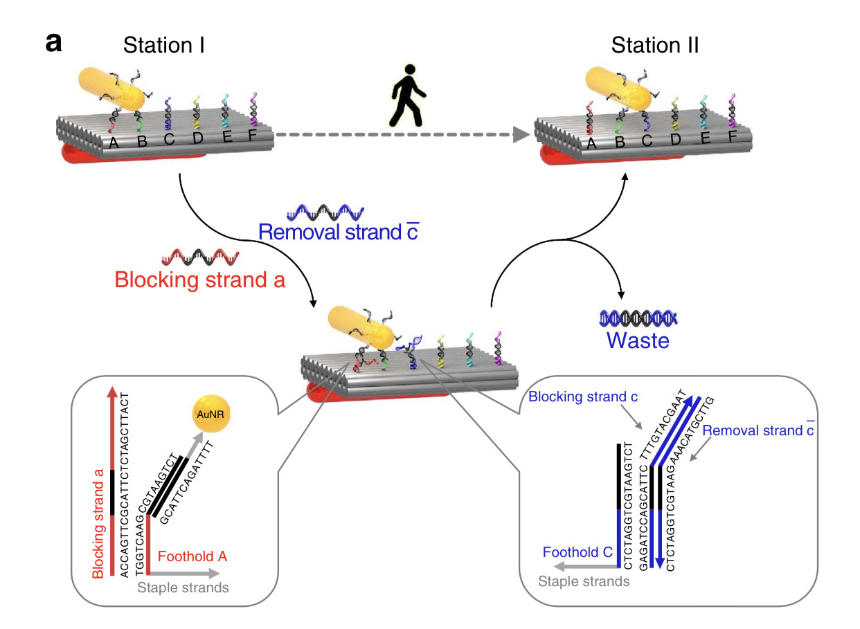
Figure 1: The above figure depicts the schematics of the strand displacement mechanism used to actuate a plasmonic nanorod that walks across a DNA origami track as published by Zhou et al (3). (Image from Zhou et. al ,(3)).

Figure 2: A. The oxDNA simulation results of the Track structure along with the schematic of the cross section of both structures. B. The principle of the strand displacement mechanism used for the actuation. C. The oxDNA simulation results of the Gear structure.
Structure Characterization
For both the gear and track, the optimal concentration of magnesium chloride (MgCl2) was defined with a MgCl2 gradient during a 2.5 day annealing ramp protocol similar
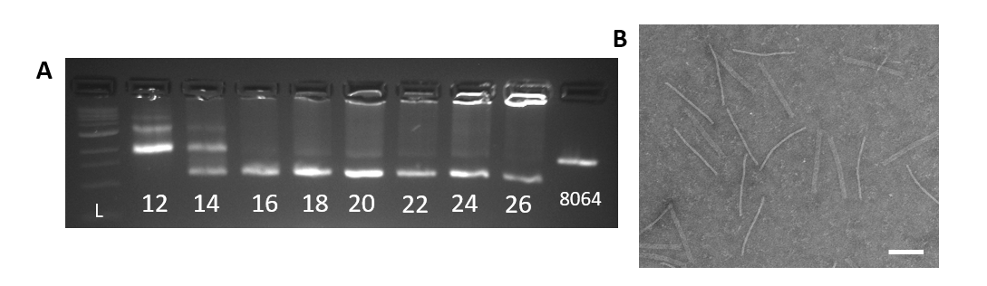
Figure 3: A. Agarose gel of the Track 2.5 day folding reaction with a MgCl2 (mM) gradient. From left to right: 1kb ladder, 12-26mM MgCl2, 8064bp scaffold. Optimal condition is 20mM MgCl2. B. TEM image of well-folded Track at 20mM MgCl2 (scale bar 100nm).
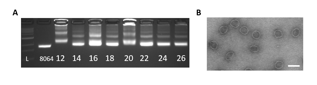
Figure 4: A. Agarose gel of the Gear 2.5 day folding reaction with a MgCl2 (mM) gradient. From left to right: 1kb ladder, 8064bp scaffold, 12-26mM MgCl2. Optimal conditions are 24mM to 26mM MgCl2. B. TEM image of well-folded Gear at 24mM MgCl2.
Once optimal MgCl2 conditions are known further structure characterization includes a 4-hour annealing ramp of a temperature gradient from 60°C-40°C in Figures 4 and 5.
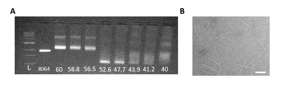
Figure 5: A. Agarose gel of the Track 4-hr folding reaction with an annealing temperature gradient (°C). From left to right: 1kb ladder, 8064bp scaffold, 60°C-40°C. Optimal annealing temperature for the Track is 52.6°C. B. TEM image of well-folded Track from a 4-hr fold at 52.6°C (scale bar 100nm).
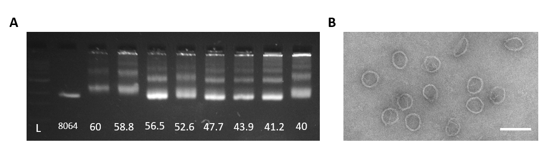
Figure 6: A. Agarose gel of the Gear 4-hr folding reaction with an annealing temperature gradient (°C). From left to right: 1kb ladder, 8064bp scaffold, 60°C-40°C. Optimal annealing temperature for the Gear is 56.5°C. B. TEM image of well-folded Gear from a 4-hr fold at 56.6°C (scale bar 100nm).
Click Arrows at top to acess next slide
Gear and Track Attachment
Gear and Track with overhangs
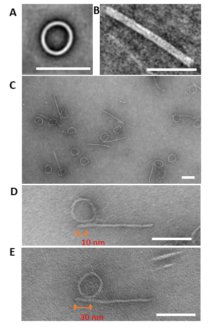
Figure 7: TEM images of the Gear and Track structures. All white scale bars represent 100 nm. A. Average image of the Gear structure. B. Average image of the Track structure. C. An image of Gear and Track structures bound. Gears are added in excess of Track. D. Gear bound to Track by the first two sites. The Gear is around 10 nm from the edge of the Track when bound at these two sites. E. Gear bound to advanced sites on Track. The Gear is around 30 nm from the edge of the Track when it is bound to the final sites.
The Gear and Track structures are designed with specific sites for overhangs. After successful characterization of the structures with overhangs, we used polyethylene glycol centrifugation (PEG) to purify excess staples from well-folded structures. After PEG purification, for binding to the location AB, blocker strands C-F are added to the Track in 10x excess relative to the Track concentration to block specific overhangs and incubated at room temperature for 30 minutes. The Gear is then added to the track in 2x excess concentration relative to the Track and incubated at 37°C for 24 hours. After incubation, part of the mixture is prepared for TEM imaging and analyzed for site AB attachment. Proof of concept shows Gear attachment to multiple sites along the Track in Figure 6. For future work using strand displacement, blocker strands for site A and unblocking strands for site C are added to detach the Gear from site A and move the Gear to site C. This technique can be used for any combination of Blocker and Removal Strands.
Click Arrows at top to acess next slide
Discussion
This project aims to design, fabricate and actuate a dynamic mechanism,consisting of a nanoscale Track and Gear. We validated the successful characterization of both structures via agarose gel electrophoresis and transmission electron microscopy (TEM). Moreover, we modified both structures with the addition of specific single stranded DNA overhangs for actuation. Using intermediate single stranded DNA blockers, we can bind the Gear to the Track and validate the successful attachments via TEM. As proof of concept for movement of the Gear along the Track we have also shown control over specific location of the binding of the Gear to the Track. The motion of the Gear on the Track resembles the motion of a rack and pinion gear system. This actuation has applications such as delivery, nano computing and transmission of material or data. In the future, we seek to explore the capabilities of our mechanism for such applications.
Click Arrows at top to acess next slide
Future Work
Future work consists of three outlooks. The first direction optimizes the binding and detachment of the Gear on the Track by varying the number of overhangs in each site. At each overhang site, there are three overhangs. This makes it challenging to remove the Gear from the Track, which results in low efficiency for actuation. We aim to investigate the effect of folding the Gear and Track with one or two overhangs at each site to analyze the efficiency of attachment, detachment, and actuation of the Gear on the Track. We hypothesis that the reduction of overhangs at each site will decrease the attachment efficiency, however, we expect a higher detachment and consequently higher actuation efficiencies. Our next direction aims to actuate the Gear across a longer scale. More overhang sites can be added to one Track allowing the Gear to move across the full length of the Track. We also seek to polymerize the Track to make longer and more complex paths for the Gear to follow. Our final direction aims to visualizing the movement or actuation of the Gear on the Track in real-time. We currently use TEM to image the static structures after actuation, however we are limited to 2-D images with no real-time visualization capability. We aim to modify our structure with FRET pair and implement single molecule microscopy to visualize the Gear and Track movement in real-time.
References
- [1] Alexander E. Marras, Lifeng Zhou, Hai-Jun Su, Carlos E. Castro: Programmable Motion of DNA origami mechanisms. PNAS 2015.
- [2] Lifeng Zhou, Alexander E. Marras, Chao-Min Huang, Carlos E. Castro, Hai-Jun Su: Paper Origami‐Inspired Design and Actuation of DNA Nanomachines with Complex Motions. Small 2018.
- [3] Chao Zhou, Xiaoyang Duan, Na Liu: A Plasmonic Nanorod that Walks on DNA Origami. Nature Communications. 2015
- [4] Jong-Shik Shin, Niles A. Pierce: A Synthetic DNA Walker for Molecular Transport.
- [5] Kevin Yehl, et al: High-Speed DNA-based Rolling Motors Powered by RNase H. Nature Nanotechnology. 2015
Click Arrows at top to acess next slide